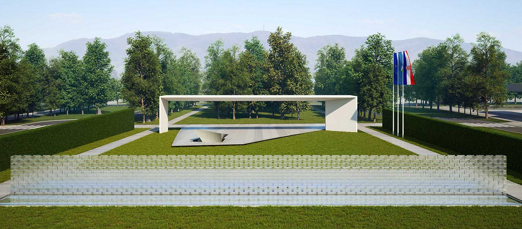
As part of the planned works on the arrangement of the Homeland Monument, the City of Zagreb hired the company Qtech design for the project of automatic irrigation system | automatic rainwater system. The system is supplied with water via the city water supply connection, which is located at the planned positions of the automatic irrigation system connection in the ventilation shafts of the fountain pumping station. The system is controlled by a digital current programmer.
Monument to the homeland
As a project deposit for the preparation of irrigation system documentation, the designer was provided with a project for arranging the green areas of the Monument to the Homeland, made by the certified landscape architect Robert Duić.

Performance dynamics
The implementation of the irrigation system of green areas is divided into two phases.
The first phase includes the construction of the supply water supply installation for irrigation, these works are performed in the construction phase of the infrastructure of the facility, before the construction of roads and paths. The works of the first phase include the installation of watertight penetrations for the passage of pipes from ventilation shafts where they are located solenoid valves to watering surfaces.
The second phase includes the construction of an irrigation system, performed in the phase of filling the final layer of soil and planting plant material, before sowing the lawn.
The works of the second phase include:
- installation of a complete pipeline starting from the connections to the supply line (performed in Phase I) to the manholes with solenoid valves,
- installation of distribution valves and solenoid valves,
- installation of lateral lines with irrigation devices (tubes drop by drop, sprayers),
- all earthworks required for the installation of plumbing and electrical installations and irrigation devices,
- all other assembly and craft works necessary for the execution of a complete and functional system,
- all actions required to connect a new automation system,
- all tests and trials required to demonstrate the functionality of the system
- all work on managing construction site documentation and making schemes of the performed state of installations
Water supply
Irrigation system it will be supplied with city water via the DN50 water supply connection with a minimum flow of 7.0 m3 / h and 4.5 bar (supply height of 45 m) located at the planned positions of the automatic irrigation system connection in the ventilation shafts of the fountain pumping station. This project includes irrigation on an area of approx. 4460 m2

Irrigation devices
Surfaces with flower beds, floor coverings and hedges are irrigated by dripping, so that the installation of a two-layer pipe with droppers with a flow rate of 2.2 l at a distance of 33 cm, with built-in pressure compensation, is envisaged. On all lateral lines s tubes drop by drop additional pressure regulators with a set outlet pressure of 2.0 bar are installed. Lawn areas are irrigated by an irrigation system using pop up sprinklers connected to the lateral line. The choice of sprayer and nozzle depends on the size of the surface to be irrigated.
 Pop up sprinkler
Management system
All controls are mounted on an outdoor installation. The irrigation system is divided into 17 zones of simultaneous operation via a solenoid valve with a diameter of DN40 (R1 1/2 ''), with a spool voltage of 24V.
Solenoid valves have the ability to manually operate and adjust the flow, and their construction prevents the return of water from the installation to the supply network. Solenoid valves are made of hard plastic, normally closed, for operating pressure up to 10 bar and medium temperature up to 43 ° C. Solenoid valves are installed in the ventilation shafts of the service room. For each solenoid valve in the system, the installation of a pressure regulator is provided to adjust the pressure in the lateral line, so that the irrigation devices work in the design conditions. The operation of the solenoid valves is controlled via a digital current programmer with a minimum of 20 control outputs 24V el. solenoid valves. The digital power programmer has an LCD display with a simple user interface, the possibility of flow control and flow control, a time sensor connection with a bypass switch, a master valve connection.
Digital current programmer
Statement of flow along lateral lines
The following are the individual flows of lateral lines in the irrigation system, under the condition of optimal hydraulic operating conditions:
- operating pressure on the lines from the pipe drop by drop - 2 bar
- operating pressure on lines with static sprinklers - 3 bar
- operating pressure on lines with dynamic sprinklers - 3 bar

Water consumption of the rainwater system of the Monument to the Homeland with 100% overlap is shown in the following diagram:

